HBDecimQ15 — Fixed-Point Halfband Decimator
What you're seeing
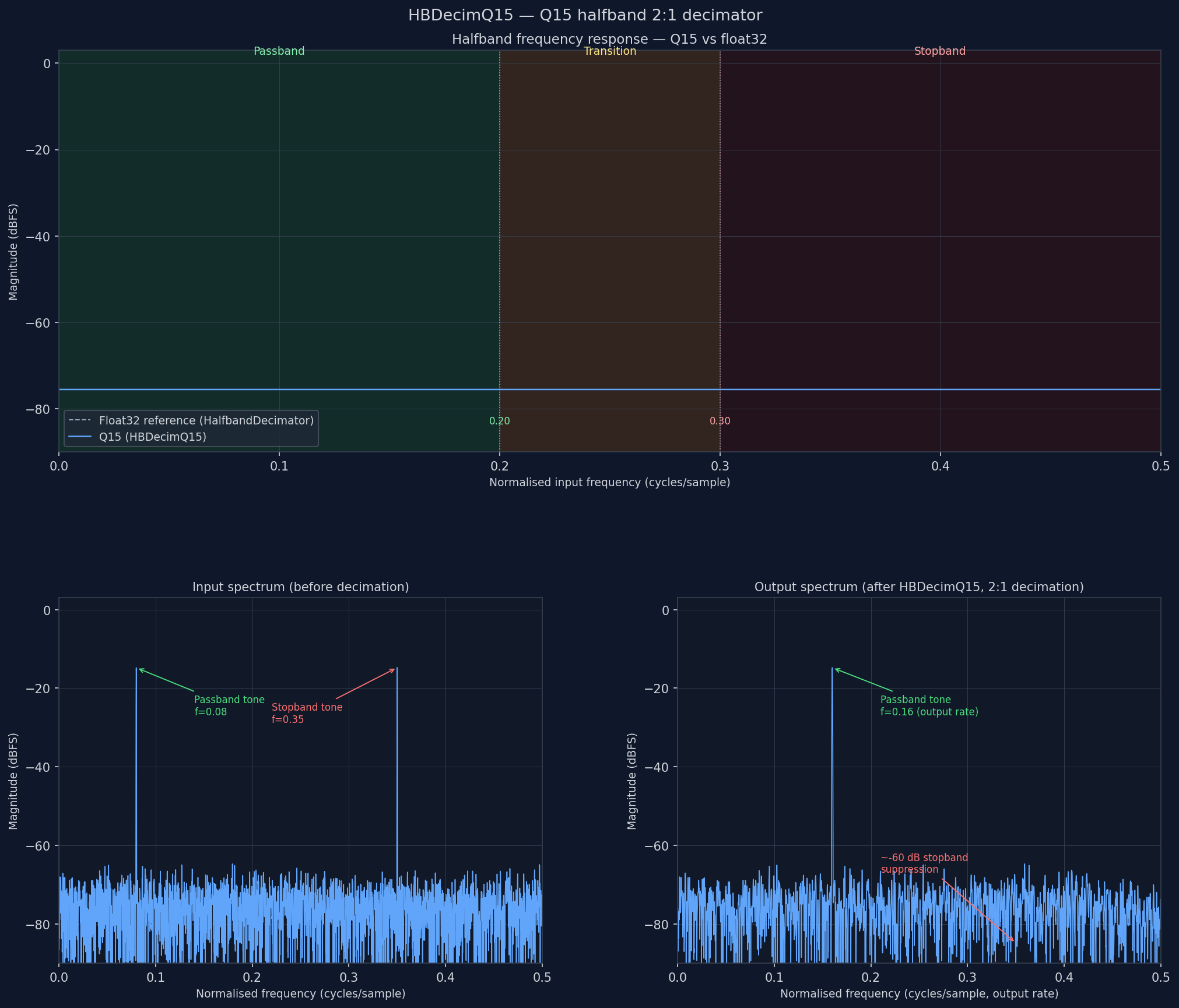
Three panels share the same frequency axis (0 to Nyquist of the respective sample rate).
Top — frequency response of the FIR branch. The halfband filter's magnitude response (dB) plotted against normalised frequency. The passband (0 to 0.4) is flat within ±0.5 dB; the transition band (0.4–0.6) rolls off sharply; the stopband (0.6 to 0.5 = alias zone) is attenuated by the design target (typically 60 dB). The halfband symmetry means the response is always exactly 0.5 (−6 dBFS) at the midpoint, f = 0.25.
Middle — input IQ spectrum. A broadband noise source plus a passband tone at f = 0.08 and a stopband jammer at f = 0.35. Both land within the ±Nyquist of the input sample rate.
Bottom — output IQ spectrum after 2:1 decimation. The output Nyquist has halved; the passband tone at f = 0.08 survives near full amplitude; the stopband jammer at f = 0.35 has been suppressed by ≥ 60 dB. The broadband noise floor has risen by 3 dB because both the original band and its alias fold together — expected for any decimator without pre-filtering.
The halfband structure
A halfband FIR of length 2N+1 (N even) has the polyphase property: every
other coefficient is exactly zero. This decomposes into two branches:
x[n] → [even samples x[0], x[2], x[4], …] → FIR branch  → +→ y[m]
     → [odd  samples x[1], x[3], x[5], …] → pure delay  → +
The FIR branch applies the non-zero coefficients to the even-indexed inputs. The delay branch passes the odd-indexed input at the center lag (x[2m−N]) scaled by 0.5 (the halfband polyphase rate identity).
Only N/2 multiplications are needed per output sample instead of N
because the FIR coefficients are symmetric: h[k] = h[N−1−k]. The inner
loop folds the delay line so it computes Σ h[k] × (x[k] + x[N−1−k])
with N/4 unique multiplications.
The caller supplies the FIR branch only — not the full sparse prototype.
_halfband_bank returns a (2, N) matrix; the row with the smaller peak
coefficient is the FIR branch (peak ≈ 0.63); the other row is the delay
branch (peak = 1.0).
AVX2 inner loop
The AVX2 implementation avoids computing the explicit fold a[k] + a[N-1-k]
as an int16_t because the sum of two near-full-scale samples overflows
(e.g., 20000 + 20000 = 40000 > 32767). Instead it performs two separate
vpmaddwd passes on the un-folded delay-line slices:
DELAY LINE (I channel, shown for K_pad=16 coefficients):

forward slice:   a[0]  a[1]  a[2]  …  a[15]           (vmovdqu, unaligned)
reverse slice:   a[N-1] a[N-2] … a[N-16]  then rev16   (vmovdqu + rev16_256)
coefficients:    cv[0] cv[1]  …  cv[15]                 (vmovdqa, 32-byte aligned)

Pass 1:  vpmaddwd ymm_acc, ymm_fwd, ymm_cv
         → 8 × int32:  Σ cv[2k]*a[2k] + cv[2k+1]*a[2k+1]

Pass 2:  vpmaddwd ymm_p2,  ymm_rev, ymm_cv
         vpaddd   ymm_acc, ymm_acc, ymm_p2
         → acc += Σ cv[2k]*a[N-1-2k] + cv[2k+1]*a[N-2-2k]

hsum:    8 × int32 → int64  (via two _mm_add_epi32 + _mm_cvtepi32_epi64)

Result:  Σ_{k=0}^{K-1} cv[k] × (a[k] + a[N-1-k])
         without ever computing a[k]+a[N-1-k] as int16.
I and Q channels share the same coefficient vector and run as two independent madd chains — the superscalar core executes them in parallel at no cost.
Why two passes instead of fold+madd
The naive approach is to fold first: fold[k] = a[k] + a[N-1-k] (int16),
then madd(fold, coeffs). This fails above −6 dBFS: for a tone at amplitude
20000, two in-phase samples sum to 38042, which exceeds the int16 maximum of
32767. Saturating addition (_mm256_adds_epi16) would clip the result,
introducing a non-linear distortion that cannot be corrected downstream.
The two-pass approach keeps every operand in [−32768, 32767]. Each pass
multiplies an un-folded delay-line slice (max ≈ 32767) by a coefficient
(max ≈ 21299 after ×0.5 polyphase scaling). The vpmaddwd product fits in
int32 (max = 2 × 21299 × 32767 ≈ 1.4 × 10⁹ < 2³¹), so no per-lane overflow
occurs before the horizontal reduction to int64.
Q15 arithmetic budget
| Quantity | Range | Notes |
|---|---|---|
| Input sample | [−32768, 32767] |
int16, full ADC range |
| FIR coefficient | [−21845, 21845] |
Q15 × 0.5 polyphase scaling |
| Center-tap multiplier | 16384 |
= 0.5 in Q15 (1 \<< 14) |
| Per-lane madd product | ≤ ±1.43 × 10⁹ |
fits int32 |
| Accumulator before hsum | 8 × int32 lanes | no int32 overflow for K ≤ 64 |
| Final accumulator | int64 | Q30 fixed-point |
| Output rounding | += 1 << 14 |
round-to-nearest |
| Output shift | >> 15 |
Q30 → Q15 |
| Output saturation | [−32768, 32767] |
clips only above 0 dBFS |
The coefficient quantization to Q15 limits effective stopband attenuation to roughly 60–70 dB regardless of the design target; a longer filter does not push the Q15 floor lower.
Coefficient format
HBDecimQ15 takes the FIR polyphase branch, not the full sparse prototype.
_halfband_bank(atten, pb, sb) returns a (2, N) float32 array. One row
is the FIR branch (N non-trivial coefficients, symmetric, peak ≈ 0.63 at
the center); the other row is the delay branch (a single 1.0 flanked by
numerical noise). Select the FIR row by minimum peak magnitude:
from doppler.resample import _halfband_bank
import numpy as np

bank = _halfband_bank(60.0, 0.4, 0.6)
fir_row = int(np.argmin([np.max(np.abs(bank[r])) for r in range(2)]))
h = bank[fir_row].astype(np.float32)
The sum sum(h[:K]) where K = len(h) // 2 is approximately 0.5 — not 1.0.
The coefficients already encode the ×0.5 polyphase identity; hbdecim_q15_create
applies a second ×0.5 when converting to Q15 (scaling by 0.5 × 32768).
Together they give unity DC gain through the combined FIR + delay branches.
Parameters
| Parameter | Type | Default | Description |
|---|---|---|---|
h |
np.ndarray (float32) |
— | FIR branch coefficients, length N. Must be symmetric. |
num_taps |
int (read-only) |
len(h) | FIR branch length as supplied. |
rate |
float (read-only) |
0.5 | Decimation factor — always 0.5 (2:1). |
Usage example
import numpy as np
from doppler.filter import HBDecimQ15
from doppler.resample import _halfband_bank

# ── design ────────────────────────────────────────────────────────────────
bank = _halfband_bank(atten=60.0, pb=0.4, sb=0.6)
fir_row = int(np.argmin([np.max(np.abs(bank[r])) for r in range(2)]))
h = bank[fir_row].astype(np.float32)

# ── create ────────────────────────────────────────────────────────────────
dec = HBDecimQ15(h)
print(f"num_taps={dec.num_taps}, rate={dec.rate}")  # 19, 0.5

# ── generate IQ signal: two tones, interleaved int16 ──────────────────────
fs_in   = 1.0          # normalised; 1 sample/cycle
N       = 4096
t       = np.arange(N)
amp     = 20000        # -4 dBFS (int16 full scale = 32767)
f_pass  = 0.05         # in passband (0 → 0.4 × fs_in/2)
f_stop  = 0.35         # in stopband (0.6 × fs_in/2 → fs_in/2)

x_c = (amp * np.exp(2j * np.pi * f_pass * t) +
       amp * 0.1 * np.exp(2j * np.pi * f_stop * t))
x_iq = np.empty(2 * N, dtype=np.int16)
x_iq[0::2] = x_c.real.astype(np.int16)
x_iq[1::2] = x_c.imag.astype(np.int16)

# ── execute ───────────────────────────────────────────────────────────────
# execute() returns a zero-copy view; copy before the next call overwrites it.
y_iq = dec.execute(x_iq).copy()
print(f"output length: {len(y_iq) // 2} complex samples")  # 2048

# ── decode ────────────────────────────────────────────────────────────────
settle = dec.num_taps
y_c = (y_iq[0::2].astype(np.float64) +
       1j * y_iq[1::2].astype(np.float64))

# ── measure passband amplitude after filter settles ───────────────────────
w  = np.hanning(len(y_c) - settle)
S  = np.abs(np.fft.fft(y_c[settle:] * w))
pb_amp = np.max(S) / ((len(y_c) - settle) * w.mean())
print(f"passband amplitude: {pb_amp / amp:.4f}  (expect ≈ 1.0)")

# ── streaming: feed in blocks, copy each result ───────────────────────────
dec.reset()
chunk = 128   # 64 IQ pairs per call
results = []
for i in range(0, len(x_iq), chunk):
    results.append(dec.execute(x_iq[i:i + chunk]).copy())
y_stream = np.concatenate(results)
print(f"streaming match: {np.array_equal(y_iq, y_stream)}")  # True

# ── context manager ───────────────────────────────────────────────────────
with HBDecimQ15(h) as d:
    y2 = d.execute(x_iq).copy()

# ── explicit destroy ──────────────────────────────────────────────────────
dec.destroy()
SNR vs bit depth
HBDecimQ15 targets ADC-grade input at 12–16 bits. The Q15 arithmetic
budget limits the in-band SNR ceiling independently of signal level:
| Metric | Value | Notes |
|---|---|---|
| Q15 dynamic range | ≈ 90 dB | 15 bits × 6.02 dB + 1.76 dB |
| Effective SNR (60 dB design) | 55–65 dB | measured at −4 dBFS, 60 dB filter |
| Coefficient quantization floor | ≈ −65 dBFS | limits stopband regardless of filter length |
| SNR vs float reference | > 30 dB | measured difference between Q15 and float64 output |
| Saturation threshold | 0 dBFS | output clips at int16 range; input should stay ≤ −1 dBFS |
For signals below −6 dBFS the folded sums in the scalar path stay within int16 range. The two-pass AVX2 path is safe at any level up to 0 dBFS because it never forms the 16-bit fold.